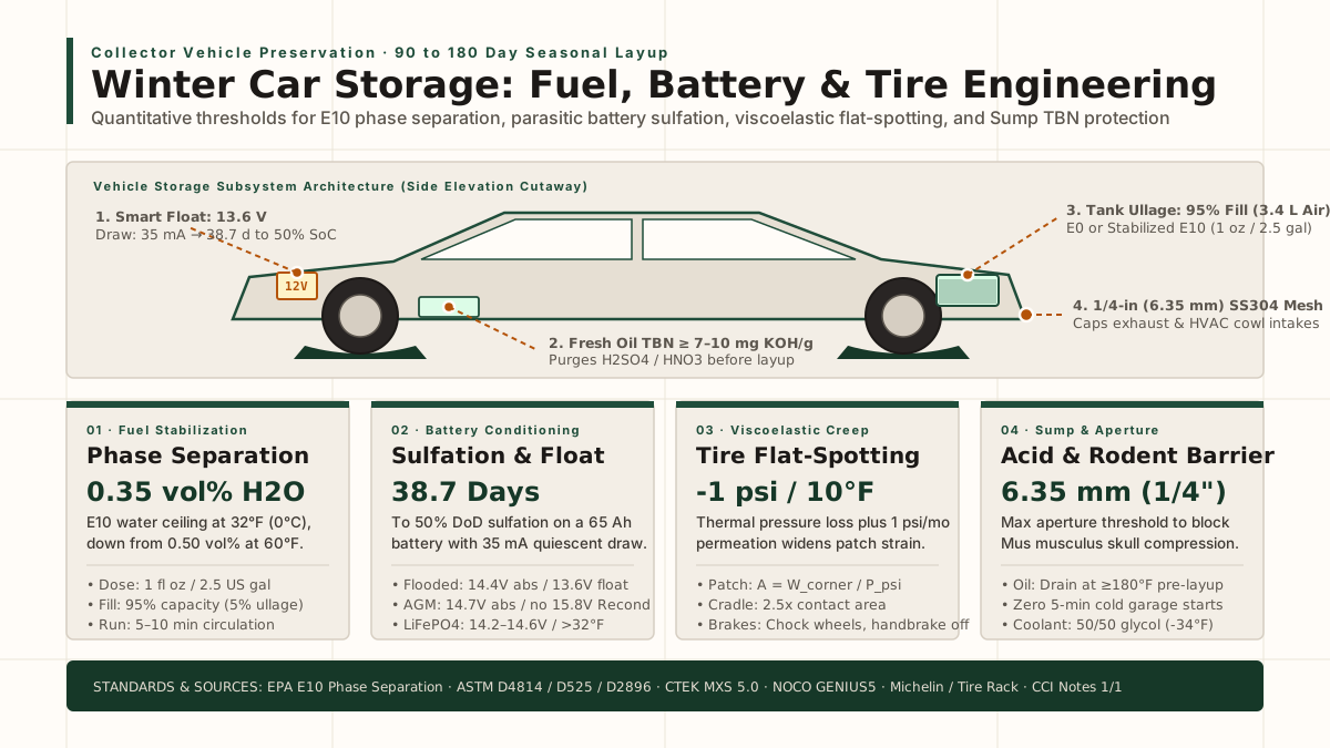
Leaving a stored collector car on an unregulated trickle charger boils off battery electrolyte, while parking it for months with the cables connected lets quiescent parasitic draw cause permanent lead-sulfate (PbSO4) plate damage below 12.40 V. Selecting between a microprocessor battery tender (classic car battery maintainer), a negative car battery disconnect switch, or a dual-isolation combination depends on bay electrical power, volatile vehicle electronics, measured key-off draw, and battery chemistry. This hardware comparison expands the electrical preservation baseline in our winter car storage fuel, battery and tire guide and pairs with the room-level receptacle checks in our collector-car storage facility checklist on the ownership costs shelf.
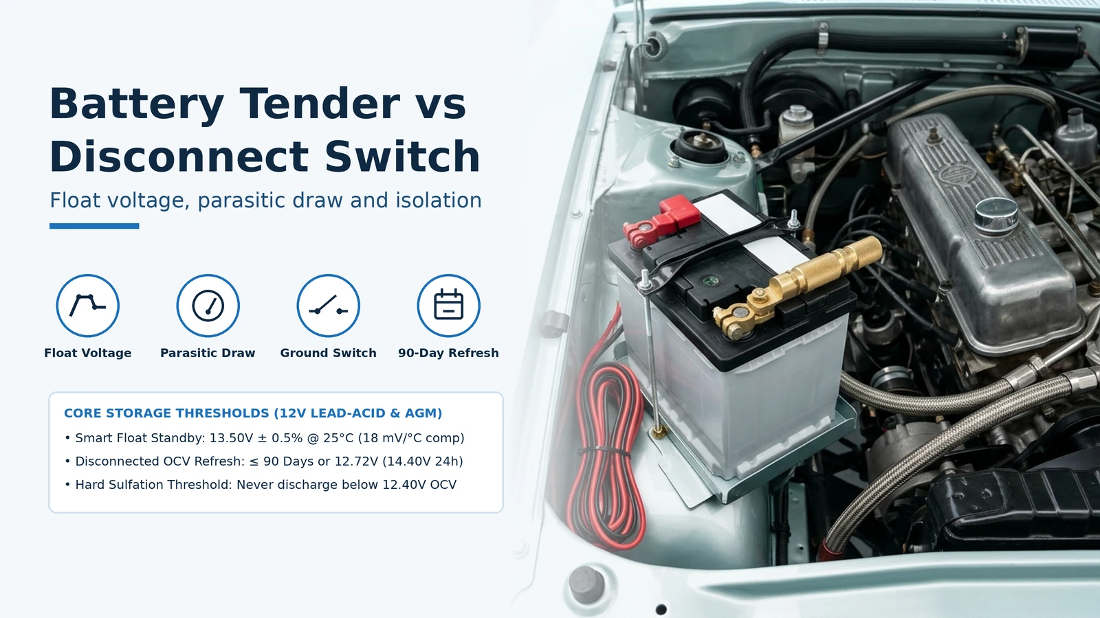
Connect a microprocessor-controlled battery tender (13.50 V to 13.60 V regulated float at 77°F / 25°C) whenever reliable 120V/240V AC wall power is available and the vehicle requires continuous power for ECU adaptations, immobilizers, alarms, or radio security codes. Install and open a manual negative car battery disconnect switch when storing a carbureted or mechanical-injection classic with zero volatile memory in an unpowered bay, logging rested Open Circuit Voltage (OCV) monthly and applying a 24-hour 14.40 V refresh charge every 90 days or whenever OCV reaches 12.72 V (6.36 V on 6 V systems). For vintage classics with unfused cloth or lacquer-braided wiring parked in a powered garage, combine both: open the negative disconnect switch to isolate the chassis harness from ground faults, and wire the smart maintainer’s fused ring-terminal pigtail directly across the battery posts.
Decision Matrix: Smart Battery Tender vs. Negative Disconnect Switch vs. Dual Isolation
Choosing the right storage architecture requires matching the vehicle’s electrical topology and storage bay infrastructure against three distinct operating modes.
| Storage Configuration | Required Bay & Vehicle Conditions | Voltage & Current Behavior | Dominant Failure Mode & Prevention |
|---|---|---|---|
| Mode A: Smart Battery Tender Connected In-Circuit ( 1.25 A to 5.0 A microprocessor float maintainer) |
Reliable 120V/240V AC receptacle; 1980s–present collector cars with volatile ECU memory, immobilizers, alarms, or digital clusters |
Steps through Bulk (constant current) and Absorption (14.4 V Wet / 14.7 V AGM) to Float standby (13.50–13.60 V at 77°F / 25°C), supplying micro-current to cover self-discharge plus 15–45 mA standby draw |
Failure mode: Unregulated trickle charger boil-off, wrong chemistry mode (15.8 V Recond on sealed AGM), or active >1 A wiring fault trapping charger in Bulk.Prevention: Verify key-off draw with a multimeter before layup and match charger chemistry mode. |
| Mode B: Negative Battery Disconnect Switch Open (Manual rotary, knife, or master terminal cutoff) |
Unpowered storage bay or elevated lift runway without AC drop cord; pre-ECU analog classics with zero volatile memory | Breaks chassis ground return (I_draw = 0 mA); battery decays solely by internal chemical self-discharge (1%–3%/mo AGM; 3%–5%/mo flooded wet cell) from 12.80 V / 12.60 V resting baseline |
Failure mode: Unmonitored multi-month self-discharge dropping OCV below 12.40 V hard sulfation threshold, or under-rated switch overheating during starter cranking.Prevention: Log 24-hour rested OCV monthly; apply 24-hour 14.40 V refresh charge at 90 days or ≤12.72 V OCV. |
| Mode C: Dual Isolation (Disconnect Open + Direct-to-Post Maintainer) (Combined switch + fused ring-terminal harness) |
Powered garage bay housing a 1950s–1970s collector car with aging, unfused cloth or lacquer-braided chassis wiring and no volatile ECU memory | Negative disconnect switch remains open (0 mA to vehicle chassis); maintainer ring terminals attach directly to positive and negative battery posts, holding battery at 13.50–13.60 V float |
Failure mode: Clipping the negative charger lead to the chassis side of an open disconnect switch (leaving the circuit open so the battery never charges). Prevention: Bolt both fused maintainer ring terminals directly to the battery's lead post clamps on the battery side of the switch. |
Conditional Selection Thresholds (Rules of Thumb)
Apply four physical verification rules before locking the garage door for the season:
- If
I_draw > 20 mAon a vehicle with volatile ECU, immobilizer, or radio memory and reliable AC power is present → prioritize Mode A (Smart Battery Tender In-Circuit) because a35 mAstandby draw (0.84 Ah/day) depletes a65 Ahbattery to its50%sulfation limit in38.7 days, whereas disconnecting the battery erases learned throttle, fuel-trim, and window-indexing states. - If the vehicle has unfused vintage wiring and zero volatile electronic memory in a powered bay → prioritize Mode C (Dual Isolation) because opening the negative disconnect switch completely de-energizes aging under-dash harnesses and electromechanical clock coils while the direct-to-post maintainer prevents plate sulfation indefinitely.
- If no
120V/240V ACoutlet is available within the charger’s DC lead reach (or the car sits on the upper runway of a 4-post storage lift without an overhead power drop) → prioritize Mode B (Negative Battery Disconnect Switch Open) paired with a scheduled bench refresh charge every90 daysor whenever rested OCV reaches12.72 V(6.36 Von6 Vsystems). - If measured key-off current exceeds the vehicle’s factory service manual sleep specification (or exceeds
100 mAafter all modules enter sleep mode) → diagnose and repair the parasitic fault before connecting a maintainer, because a1.25 Afloat charger is designed to offset normal self-discharge, not mask a shorted glovebox lamp or leaking alternator diode.
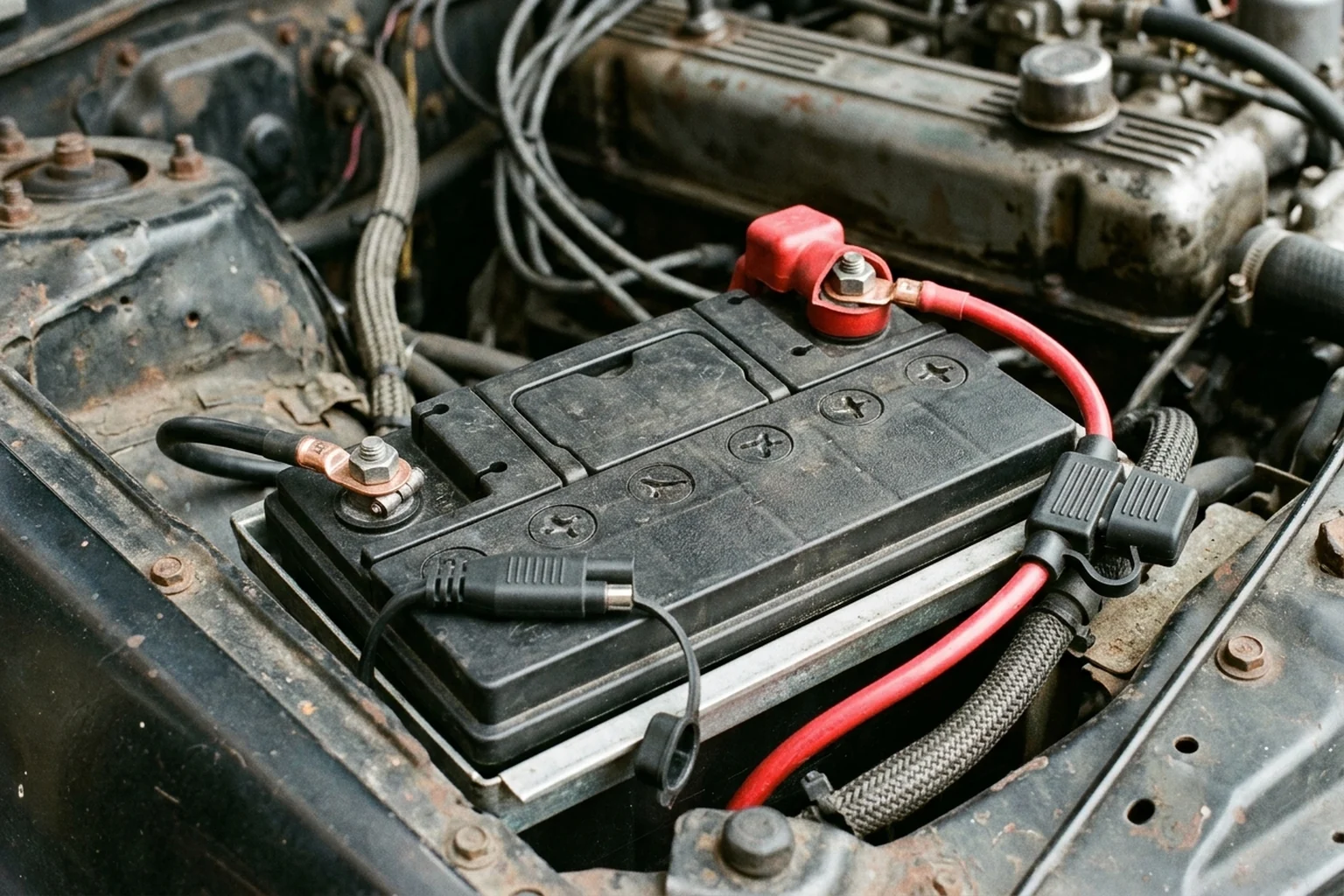
Selection takeaway: Never treat a battery tender and a negative disconnect switch as mutually exclusive on an analog classic—bolting the maintainer’s fused ring terminals directly to the battery posts while opening a negative-post disconnect switch delivers both 13.50–13.60 V electrochemical float protection and 0 mA chassis harness isolation.
Multi-Stage Float Voltage Physics vs. Unregulated Trickle Chargers
In everyday garage conversation, owners often use “trickle charger” and “battery tender” (classic car battery maintainer) interchangeably. Electrically, they operate on opposite control principles, and connecting an unregulated trickle charger for a 90-to-180-day layup destroys lead-acid and AGM batteries.
How a 4-to-8-Step Microprocessor Maintainer Prevents Boil-Off
As documented in Deltran Battery Tender’s Understanding the 4-Step Charging Process and Battery Tender Plus 12V 1.25A technical specifications, alongside CTEK’s MXS 5.0 8-step engineering datasheet, a microprocessor-controlled maintainer regulates both current and terminal voltage across four primary electrochemical phases:
- Initialization & Qualification (Desulfation / Soft Start): Before any charging current flows, the microprocessor verifies battery continuity, minimum terminal voltage (
2.0 Vstart threshold on the CTEK MXS 5.0;1.0 Vauto-sensing or0 Vmanual force mode on the NOCO GENIUS5), and correct polarity. Deltran’s initialization stage applies a couple-hundred milliamps up to a~14.6 Vtarget check; until polarity is confirmed, spark-proof circuitry keeps the leads de-energized to protect vehicle ECUs and alternators. - Bulk Stage (Constant Current to
~80%SoC): Once qualified, the charger delivers its maximum rated constant current (1.25 Aon the Deltran Battery Tender Plus for14–80 Ahbatteries;4.0 Aon the Deltran Power Tender 4A for14–100 Ah;4.3 A/5.0 Aclass on the CTEK MXS 5.0 and NOCO GENIUS5 for up to110–120 Ah) while battery terminal voltage steadily climbs toward the absorption threshold (~14.4 V to 14.5 V). - Absorption Stage (Constant Voltage, Tapering Current from
80%to100%SoC): When terminal voltage hits the chemistry-specific peak (14.4 Vin CTEK Normal wet-cell mode;14.7 Vin AGM mode;13.80–14.60 Vat77°F / 25°Cunder East Penn Manufacturing VRLA AGM & Gel Installation and Operating Manual No. 1833), the charger clamps voltage constant. As internal plate conversion completes and internal resistance rises, charging current tapers smoothly down to a few hundred milliamps, preventing thermal runaway and plate gassing. - Float / Pulse Maintenance Stage (
100%SoC Standby): Once current tapers to the completion threshold, the maintainer drops terminal voltage to a tightly regulated standby level:13.50 V ± 0.5%(13.43 V to 13.57 V) at77°F (25°C)per East Penn Manual No. 1833, or13.6 VFloat followed by12.9 V to 14.4 VPulse monitoring on the CTEK MXS 5.0. In Float mode, the unit supplies only the micro-current required to offset internal self-discharge and milliamps of vehicle keep-alive draw.
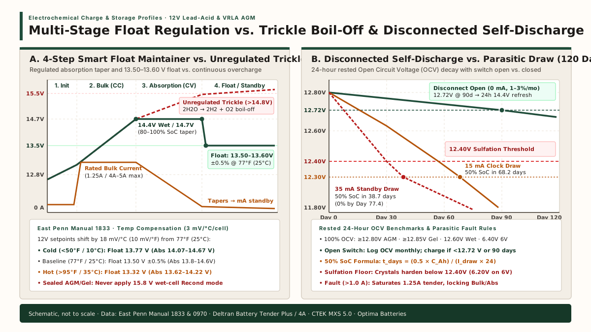
By contrast, a cheap, unregulated constant-current trickle charger uses a basic step-down transformer and rectifier without voltage feedback (Deltran Battery Tender Plus Technical Specifications). When connected to a fully charged battery for two weeks or an entire winter, it continues forcing 1 A to 2 A into saturated plates, driving terminal voltage above 14.8 V to 15.5+ V. That excess potential decomposes water in the electrolyte via continuous electrolysis (2H2O → 2H2 + O2), generating heat, corroding positive lead grids, boiling dry vented flooded cells, and forcing recombinant oxygen and hydrogen out through the one-way pressure-relief valves of sealed VRLA AGM and Gel batteries.
Multi-Chemistry Voltage Profiles & Ambient Temperature Compensation (3 mV/°C/cell)
Lead-acid electrochemistry shifts directly with battery construction (Flooded, AGM, Gel, 6V vs. 12V) and garage ambient temperature. Selecting the wrong charger mode—or using a fixed-voltage charger in an unheated freezing barn or a hot summer warehouse—causes chronic undercharging or overcharge grid corrosion.
| Battery Chemistry & Nominal System | 24-Hour Rested 100% SoC OCV | Absorption Stage Setpoint (at 77°F / 25°C) | Float / Standby Setpoint (at 77°F / 25°C) | Thermal Compensation & Mode Restrictions |
|---|---|---|---|---|
| 12V Flooded Lead-Acid (Vented Wet Cell, Antimony or Ca/Ca) |
~12.60 V to 12.66 V(Optima / industry 6-cell baseline) |
14.40 V(CTEK MXS 5.0 Normal mode) |
13.50 V to 13.60 V( 12.9–14.4 V pulse top-up) |
Subtract 18 mV/°C above 25°C; add 18 mV/°C below 25°C. 15.8 V / 1.5 A Recond permitted only on vented wet cells after checking distilled water level. |
| 12V VRLA AGM (8A) & Gel (8G) (Sealed Recombinant Valve-Regulated) |
≥12.80 V (AGM)≥12.85 V (Gel)13.0–13.2 V (Spiral AGM) |
13.80 V to 14.60 V (East Penn)14.70 V (CTEK AGM mode) |
13.50 V ± 0.5%( 13.43–13.57 V East Penn; 13.60 V CTEK) |
18 mV/°C (10 mV/°F) shift: 13.77 V float at <50°F (10°C); 13.32 V float at >95°F (35°C). Never use 15.8 V Recond/Equalize on sealed AGM or Gel. |
| 6V Vintage Lead-Acid / AGM (3-Cell Series Pre-1960s Antiques) |
≥6.40 V (AGM)~6.30 V (Flooded Wet) |
6.90 V to 7.30 V(East Penn 6V rule: half of 12V) |
6.75 V ± 0.5%( 6.72–6.78 V at 77°F / 25°C) |
9 mV/°C (5 mV/°F) shift per 3-cell 6V battery. Requires dedicated 6V charger mode (such as Deltran Power Tender 4A 6V/12V or NOCO GENIUS5 6V mode). |
| 12V LiFePO4 (Lithium Iron Phosphate) (12.8V Nominal 4S with Internal BMS) |
13.30 V to 13.40 V(Rested 4-cell LiFePO4) |
14.20 V to 14.60 V(Dedicated CC/CV Lithium profile) |
Chemistry-specific Lithium maintenance (zero desulfation pulses) | Requires dedicated 12V Lithium mode (Deltran Power Tender 4A or NOCO GENIUS5). Never use lead-acid desulfation pulses (15.8 V) and never charge below 32°F (0°C). |
Worked Temperature Compensation Formula (V_comp)
According to East Penn Manufacturing Manual No. 1833 (Section Temperature Compensation and Appendix B Voltage Compensation Chart), lead-acid charge and float voltages must be adjusted by 3 mV per °C (1.8°F) per cell relative to the 77°F (25°C) reference baseline. For a 6-cell 12 V battery, that equals 18 mV per °C (0.018 V/°C or 10 mV/°F); for a 3-cell 6 V battery, 9 mV per °C (0.009 V/°C):
V_comp(12V) = V_25C - 0.018 × (T_ambient_C - 25)
Applying East Penn’s equation and Appendix B table across winter and summer storage conditions demonstrates why automatic temperature compensation (built into units such as the Deltran Battery Tender Plus, Deltran Power Tender 4A, CTEK MXS 5.0, and NOCO GENIUS5) matters:
- Example calculation (Cold winter garage at
10°C / 50°Fand below,V_25C = 13.50 Vfloat):V_comp = 13.50 V - 0.018 V/°C × (10°C - 25°C) = 13.50 V + 0.27 V = 13.77 VCold electrolyte exhibits higher internal resistance; raising float voltage to13.77 V(and absorption voltage to14.07–14.67 V) prevents chronic winter undercharging and sulfate accumulation. - Example calculation (Hot summer storage bay at
35°C / 95°F,V_25C = 13.50 Vfloat):V_comp = 13.50 V - 0.018 V/°C × (35°C - 25°C) = 13.50 V - 0.18 V = 13.32 VLowering float voltage to13.32 V(and absorption to13.62–14.22 V) prevents thermal gassing. East Penn also notes an Arrhenius durability boundary: every13°F (7°C)increase in average operating temperature above77°F (25°C)reduces battery operating life and warranty coverage by50%.
Calculation takeaway: Verify that your battery maintainer incorporates ambient temperature compensation (18 mV/°C for 12 V or 9 mV/°C for 6 V), and never activate a 15.8 V wet-cell reconditioning step on a sealed AGM or Gel battery.
Parasitic Draw Depletion, Sulfation Below 12.40 V & Pre-Layup Multimeter Audit
Whether you leave a battery connected in the car or isolate it with a car battery disconnect switch, lead-acid plate health is governed by a strict voltage floor. As Optima Batteries (Basic Information on Battery Voltage) and Deltran document, whenever any 12V lead-acid or AGM battery discharges below 12.40 V, amorphous lead sulfate converts into hard, non-conductive crystalline PbSO4 on the battery plates. Once hard sulfation crystallizes across the active plate material, charging cannot restore the lost amp-hour capacity.
Rested 24-Hour Open Circuit Voltage (OCV) vs. State of Charge
Per East Penn Manufacturing Manual No. 1833, a battery’s true Open Circuit Voltage (OCV) can only be determined after the battery has been completely isolated from charging and discharging loads for 24 hours so surface charge dissipates.
| State of Charge (SoC) | 12V VRLA AGM (East Penn 8A) | 12V VRLA Gel (East Penn 8G) | 12V Flooded Wet Cell | 6V Battery Equivalent (AGM / Gel) | Storage Action & Sulfation Status |
|---|---|---|---|---|---|
| 100% Charged | ≥12.80 V( 13.0–13.2 V Spiral AGM) |
≥12.85 V |
~12.60 V to 12.66 V |
≥6.40 V (AGM)≥6.42 V (Gel) |
Ready for layup. Connect float maintainer or open negative disconnect switch. |
| ~85%–90% (Refresh Trigger) | 12.72 V |
12.72 V |
~12.50 V |
6.36 V |
Mandatory East Penn refresh threshold: Charge for 24 hours at 14.40 V (7.20 V for 6V) if OCV drops below 12.72 V or at 90 days. |
| 75% Charged | 12.60 V |
12.65 V |
~12.45 V |
6.30 V / 6.32 V |
Approaching sulfation boundary on flooded cells; recharge immediately before storage. |
| ~60%–65% (Sulfation Onset) | 12.40 V |
12.40 V |
12.40 V |
6.20 V |
Critical Sulfation Line (Optima): Below 12.40 V, permanent crystalline PbSO4 forms on plates. |
| 50% Charged | 12.30 V |
12.35 V |
~12.20 V |
6.15 V / 6.17 V |
Deep discharge limit (50% DoD); prolonged storage causes irreversible capacity loss. |
| 25% Charged | 12.00 V |
12.00 V |
~11.95 V |
6.00 V |
Severely sulfated; high risk of electrolyte freezing in cold unheated bays. |
| 0% Charged | 11.80 V |
11.80 V |
<11.80 V |
5.90 V |
Dead battery; dilute electrolyte (~1.100 SG) freezes at +15°F to +19°F (-9°C to -7°C). |
Disconnected Self-Discharge vs. Connected Parasitic Depletion (t_days)
As derived in our winter car storage fuel, battery and tire preservation guide, the time in days (t_days) for a connected quiescent draw (I_draw in amperes) to drain 50% of a battery’s rated capacity (C_Ah in amp-hours) is:
t_days = (0.5 × C_Ah) / (I_draw × 24)
Comparing connected key-off draws against an open disconnect switch illustrates why both parasitic current and internal self-discharge must be managed:
- Connected 1990s–2010s Modern Classic (
C_Ah = 65 Ah,I_draw = 35 mA = 0.035 A): Alarm, immobilizer, keyless entry, and ECU keep-alive memory draw0.84 Ah/day, exhausting the32.5 Ahusable50%reserve in38.7 days(32.5 / 0.84) and reaching0%by Day 77.4. - Connected 1960s–1970s Analog Classic (
C_Ah = 60 Ah,I_draw = 15 mAclock +4%/monthself-discharge =0.44 Ah/day): Crosses the30.0 Ah(50%SoC) sulfation threshold in68.2 days(30.0 / 0.44). - Disconnected Battery with Switch Open (
I_draw = 0 mA, internal self-discharge only): Opening a negative disconnect switch eliminates the0.36 to 0.84 Ah/dayvehicle draw, but internal chemical self-discharge continues at1% to 3% per monthin VRLA AGM batteries and3% to 5% per monthin flooded antimony/calcium batteries. Under East Penn Manual No. 1833 and High-Rate Manual No. 0970, disconnected batteries stored indoors at0°F to 77°F (-18°C to 25°C)must receive a refresh charge at least every6 months, while bays reaching78°F to 90°F (26°C to 32°C)require monthly OCV measurements and a 24-hour constant-voltage refresh charge at14.40 V(7.20 Vfor 6V) within3 months (90 days)or whenever OCV drops below12.72 V(6.36 Vfor 6V).
How Active Wiring Faults Overwhelm a Battery Tender & How to Measure Draw
A 0.75 A or 1.25 A smart maintainer is engineered to supply milliamps of float current after the battery reaches 100% SoC. If a classic car has an undiagnosed wiring fault—such as a trunk or under-hood lamp switch that fails to open (~1.0 A to 2.0 A), a stuck relay coil (~0.25 A to 0.50 A), or a leaking alternator rectifier diode (~0.5 A to 3.0 A)—that continuous load consumes most or all of the charger’s output. Because net current flowing into the battery never tapers down to the milliamps absorption cutoff, the maintainer stays locked at 14.4 V to 14.7 V Bulk/Absorption voltage indefinitely or trips its internal safety timer, slowly cooking the battery.
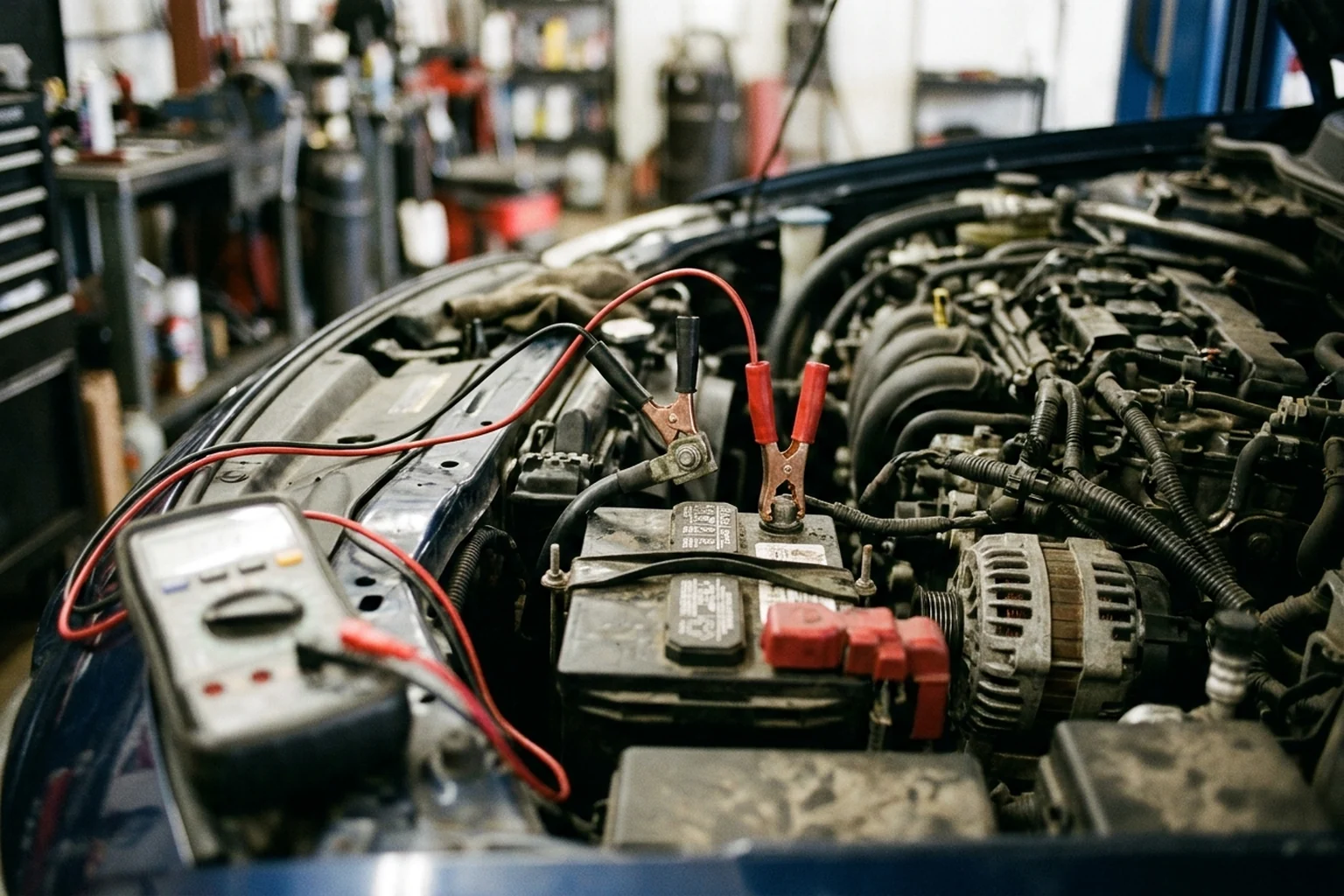
Because permissible key-off standby current varies widely by vehicle era and factory electronics, never rely on a generic milliamp rule of thumb. Before placing a vehicle on a maintainer, verify key-off current using a calibrated digital multimeter (0.05% DC accuracy class calibrated to NIST traceable standards per East Penn Manual No. 1833):
- Turn off the ignition, close all doors and trunk latches (or manually latch the striker switches so courtesy lights extinguish), and wait for any onboard modules to enter full sleep mode.
- Plug the multimeter’s red test lead into the
10A(or10A / mAfused) current jack, set the dial to DC Amps/Milliamps, and connect the meter in series between the unbolted negative (-) battery cable lug and the negative (-) battery terminal post. - Never crank the starter or turn on headlights while the multimeter is bridged in series across the terminal, or you will blow the meter’s internal fuse.
- Compare the stabilized milliamp reading directly against the specification printed in your vehicle’s factory workshop manual. An analog carbureted classic with a mechanical ignition switch and an unwound clock should read
0.0 mA.
Diagnostic takeaway: Always measure 24-hour rested OCV (≥12.80 V AGM / ≥12.60 V flooded) and series key-off milliamp draw before storage; if a battery is stored disconnected, log OCV monthly and recharge for 24 hours at 14.40 V whenever voltage reaches 12.72 V or at 90 days.
Negative Battery Disconnect Switch Engineering, Sizing & Installation
When a collector car is stored in an unpowered garage bay, parked on the upper deck of a four-post lift without an AC drop cord, or equipped with original unfused cloth wiring, a manual car battery disconnect switch provides positive mechanical isolation—provided the switch is installed on the correct terminal and rated for starter cranking surge.
Why Negative Terminal Isolation Is Mandatory (and the Positive-Ground Exception)
On any negative-ground vehicle, a storage battery disconnect switch must be installed on the negative (-) battery terminal post (EDS Parts & Concept Car Storage engineering guidelines):
- Zero Wrench-to-Chassis Arc Hazard: The vehicle’s entire steel body shell, frame rails, and engine block are bonded to the negative battery terminal. When loosening a clamp or mounting a switch on the negative post, a wrench that slips and touches a fender bracket or radiator support contacts the same electrical potential (
0 Vground reference) and cannot spark. Mounting an uninsulated metal disconnect switch on the positive (+) post creates an exposed+12 Vbusbar where any accidental metal contact to the body causes a dead short. - Complete Return-Path Interruption: Because electric current requires a closed loop between the positive post and negative post, opening the negative ground connection interrupts 100% of vehicle chassis circuits—provided no aftermarket accessories are wired directly to the negative battery post ahead of the switch.
- Pre-1960s Positive-Ground Antique Exception: Many pre-1960s British, American, and antique vehicles (both
6 Vand12 V) were built with positive-ground electrical systems where the positive (+) battery post is bolted to the chassis frame. Before ordering a tapered top-post disconnect switch (positive and negative SAE battery posts have different cone diameters:17.5 mm / 11/16 innegative vs.19.5 mm / 3/4 inpositive), verify chassis ground polarity on the battery and isolate the grounded chassis return post first.

Cranking Amp Sizing, Terminal Torque & the Alternator Load-Dump Rule
A storage disconnect switch installed in the main battery ground path sits directly in series with the starter motor. When you close the switch in spring and turn the ignition key, the switch contacts must carry the starter’s full locked-rotor inrush (150 A to >600 A depending on engine displacement and compression) plus continuous alternator charging current.
| Disconnect Hardware Parameter | Engineering Specification & Basis | Consequence of Under-Sizing or Misuse | Verification & Installation Protocol |
|---|---|---|---|
| Continuous vs. Cranking Current Rating | Match continuous rating (typically 125 A to 300+ A) to alternator/accessory load and intermittent/cranking rating (500 A to 1,000+ A) to starter surge |
Light-duty bargain thumb-wheel switches develop high contact resistance, drop cranking voltage during cold starts, and melt or pit under V8 starter load | Select heavy-duty copper/brass rotary master switches or solid copper knife switches rated above starter cranking draw; avoid cutting original collector cables where bolt-on post adapters fit. |
| Terminal Contact Cleaning & Hardware Torque | Torque terminal connections to 100 ± 5 in-lb (11.3 ± 0.5 N·m); connection resistance within 10%–20% of baseline (East Penn Manual 1833) |
Loose or oxidized switch lugs cause voltage drop across the connection, slow starter cranking, and localized terminal heating | Clean post and lug mating faces with a non-metallic brush/pad, apply approved oxide inhibitor (such as No-Ox-ID "A" per East Penn), torque to specification, and verify micro-ohm resistance annually. |
| Alternator Load-Dump Prohibition | Never open a single-pole battery disconnect switch while the engine is running | Abruptly removing the battery's capacitive load from a spinning alternator creates an instantaneous high-voltage transient ("load dump") that destroys rectifier diodes, regulators, and ECUs | Shut off the ignition and wait for the engine to come to a complete stop before opening a storage disconnect. Motorsports emergency shutoffs require a dedicated multi-pole alternator-field/main cutoff switch. |
| Multi-Battery & Auxiliary Feed Mapping | Isolate all parallel batteries or auxiliary solar/trailer feeds simultaneously; charge series strings together (East Penn Manual 1833) | Turning off one battery in a dual-battery setup or leaving an auxiliary lead attached on the battery side of the switch allows backfeeding and continued parasitic drain | Trace all ring terminals at the battery before installation; attach only the direct smart maintainer pigtail (if using Mode C) on the battery side of the disconnect switch. |
Installation takeaway: Size any main-cable battery disconnect switch for full starter cranking amps, torque terminal hardware to 100 ± 5 in-lb (11.3 ± 0.5 N·m), and never open a single-pole battery switch while the engine is running.
Layup Duration, Parasitic Draw & Float vs. Disconnect Selection Checklist
Use the printable verification checklist below before placing a collector vehicle into 30-day, 90-to-180-day, or multi-month storage. File the completed record alongside your seasonal fluid and tire notes from our winter car storage guide, your room inspection entries from the storage facility checklist, and your ongoing expenditure files on the collector-car total cost worksheet and support equipment life-cycle cost sheet (structured under 10 CFR Part 436 Subpart A).
| Audit Step & Field | Measured / Verified Value | Target Benchmark / Engineering Rule | Owner Sign-Off & Notes |
|---|---|---|---|
| 1. Vehicle & Polarity Identity | Year / Make / Model: ______________System: [ ] 12V [ ] 6VGround: [ ] Neg (-) [ ] Pos (+) |
Verify chassis ground post marking before clamping charger leads or ordering a post disconnect switch | [ ] Verified |
| 2. Battery Chemistry & Capacity | [ ] Flooded Wet [ ] VRLA AGM [ ] Gel [ ] LiFePO4Rated Capacity: ______ Ah · Installed: ____/____ |
Match charger amp rating (`1.25 A` for `14–80 Ah`; `4.0–5.0 A` for `14–120 Ah`) and exact chemistry mode | [ ] Verified |
| 3. 24-Hour Rested Pre-Layup OCV | Rested OCV: ________ V DC(Measured 24h off charge/load) |
≥12.80 V (12V AGM), ≥12.85 V (Gel), ≥12.60 V (Flooded), or ≥6.40 V (6V AGM). Never store below 12.40 V |
[ ] Full SoC Confirmed |
4. Key-Off Series Parasitic Draw (I_draw) |
Measured Draw: ________ mAFactory Manual Spec: ________ mA |
Measure in series at negative post with a 0.05% DC accuracy DMM after module sleep. Repair any >100 mA or out-of-spec fault |
[ ] Within Factory Spec |
| 5. Bay AC Power & Ambient Temp Range | AC Outlet at Bay: [ ] Yes [ ] NoExpected Temp: ______°F to ______°F |
Ideal storage 50°F–77°F (10°C–25°C); verify charger thermal compensation (`18 mV/°C` for 12V: `13.77 V` at `<50°F`, `13.32 V` at `>95°F`) |
[ ] Verified |
| 6. Selected Storage Mode (Check One) | [ ] Mode A: Smart Float Maintainer In-Circuit[ ] Mode B: Negative Disconnect Switch Open[ ] Mode C: Dual Isolation (Switch Open + Direct Post Float) |
Mode A: verify `13.50–13.60 V` Float transition & `15.8 V` Recond OFF on AGM. Mode B/C: torque terminal lugs to `100 ± 5 in-lb (11.3 ± 0.5 N·m)` |
[ ] Configured |
| 7. 30 / 60 / 90-Day Storage Inspection Log | Day 30 OCV / Float: ________ V (Date: ____/____)Day 60 OCV / Float: ________ V (Date: ____/____)Day 90 OCV / Float: ________ V (Date: ____/____) |
Mode A/C: Confirm green Float LED & `13.32–13.77 V` terminal voltage. Mode B (Disconnected): Mandatory 24h `14.40 V` (`7.20 V` for 6V) refresh charge at 90 days or if OCV drops to `≤12.72 V` (`6.36 V`) |
[ ] Logged |
Primary Technical Manuals & Reference Standards Cited in This Guide
- East Penn Manufacturing Co. / Deka: Valve Regulated Lead-Acid (VRLA) AGM (8A) and Gel (8G) Installation & Operating Manual, Manual No. 1833 (Rev. 11/20) — 24-hour rested OCV vs. SoC table (
12.80 Vto11.80 V),13.50 V ± 0.5%float and13.80–14.60 Vabsorption voltages at77°F (25°C),3 mV/°C/cell(18 mV/°Cper 12V battery) ambient temperature compensation chart (Appendix B),12.72 V(6.36 Vfor 6V) / 3-month disconnected refresh charge protocol (24 hours at 14.40 V),100 ± 5 in-lb (11.3 ± 0.5 N·m)terminal torque, and0.05%DC accuracy NIST-traceable multimeter requirements. - East Penn Manufacturing Co. / Deka: VRLA Stationary & Storage High-Rate Installation and Operating Manual, Manual No. 0970 — disconnected storage temperature intervals (
0°F–77°Fvs.78°F–90°F) and12.72 Vrefresh charging rules. - Deltran Corporation (Battery Tender): Understanding the Battery Tender 4-Step Charging Process, Battery Tender Plus 12V 1.25A Charger & Maintainer Specifications (
14–80 Ah), and Power Tender 4 Amp 12V/6V Selectable Lead-Acid & Lithium Charger Specifications (14–100 Ah) — 4-step ISM sequence (Initialization, Bulk, Absorption, Float), unregulated trickle charger overcharge boil-off comparison, and spark-proof / reverse-polarity safety logic. - CTEK Sweden AB: MXS 5.0 NA 12V Battery Charger and Maintainer Technical Specifications — 8-step charging curve (
2.0 Vminimum start,4.3 A / 5.0 Aclass for1.2–110 Ahcharging and160 Ahmaintenance), Normal wet-cell (14.4 V), AGM (14.7 V), Recond (15.8 Vvented wet-cell only), and Float (13.6 V) / Pulse (12.9–14.4 V) setpoints. - The NOCO Company: GENIUS5 5-Amp 6V/12V Smart Battery Charger Technical Specifications — multi-chemistry modes (
6V/12VWet, Gel, MF, CA, EFB, AGM, and12V Lithiumup to120 Ah), integrated thermal sensor (-4°F to 104°Foperating range), and1.0 V/0 Vlow-voltage sensing. - Optima Batteries (Clarios): Basic Information on Battery Voltage —
12.60 Vsix-cell flooded vs.13.0–13.2 Vspiral-cell AGM resting voltage and the12.40 Vlead-sulfate (PbSO4) crystallization onset threshold.